Instrument Feedthroughs
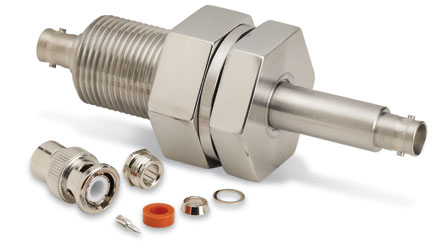
Instrument feedthroughs are specifically designed to transfer low-current, low- or high-voltage signals from low- or high-impedance sources across the vacuum wall. They have one or multiple conductors ("pins") that are terminated on the air-side in a standard electrical plug/socket ("single-ended feedthrough"). Some types also have connector terminations on the vacuum-side ("double-ended").
Single-pin feedthroughs are often coaxially shielded and intended for applications where the signal source is close to ground (earth) potential but has a high impedance and is susceptible to induced electrical noise.
The standard coaxial plug options are BNC, MHV, various SHVs, N, Microdot, SMA, and SMB. The characteristics and wiring instructions for each are described on the connector's product introductory page.
Versions of various feedthrough types have floating shields' used when transferring signals from sources at high potential-requiring the shield be separately powered to similar potential. To make the complete cable effective, coaxial connectors must be of similar impedance to the cable. (see Coaxial Cables)
Multi-pin feedthroughs, which are not coaxially shielded, are used for low impedance sources where induced noise is less significant. Most single-ended instrument feedthroughs are supplied with the air-side mating connector. Double-ended feedthroughs are not supplied with the vacuum-side connectors.
When choosing an instrumentation feedthrough, there are many critical issues, depending on the application: maximum voltage cable-to-shield, maximum voltage shield-to-ground (for isolated shields), grounding/isolation, signal voltage, impedance, temperature range, number of connections, connectors, etc. It is always prudent to confirm which connectors are or are not supplied.
Coaxial Cables
A coaxial cable has a center conductor insulated from a conducting outer shield. This construction shields the central conductor against inductive "pickup" (noise) from outside sources and provides stable, repeatable signal transmission. But equally, it shields sensitive electronic equipment from radiation emanating from the central conductor.
In vacuum applications coaxial cables typically carry measurement signals.
A coaxial cable's main characteristic is its impedance (the "total opposition to the flow of alternating current along the cable" expressed in ohms). The impedance is a function of the diameter and spacing of conductors and the insulator's dielectric constant, but not a function of its length.
The most frequently used impedance in vacuum application is 50 ohm, with cable identifications such as RG8/U, RG58/U, RG6, and RG580. For any impedance cable, the maximum (signal) power transfer occurs where the "load" equals the cable's impedance.
Normal coaxial connectors have impedance close to the cable's impedance, typically within a range of 48-52 ohms. However, matched connectors with 50-ohm impedance are available.


